- Using the C# code to directly access the Primitive Modules.
- Generating a ScriptableObject GraphAsset, with the also generated EdgeAssets and NodeAssets that will interact with primitives automatically.
- Using the GraphViewEditor to automatically generate the graph system.
Life Cycle
For the graph/node system, the life cycle of the runtime (When you actually click thePlay button) is like this:
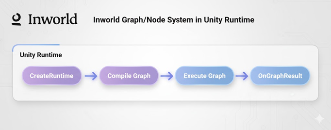
InworldGraphExecutor to hold the GraphAsset, it will do the above steps.
You will also need a NodeTemplate to communicate with the InworldGraphExecutor, to send and receive the data from Inworld.
Clone a Scene
In this overview, let’s focus on the graph creating, so we will use the current default GraphNodeTemplate in the demos.
Let’s clone a scene from 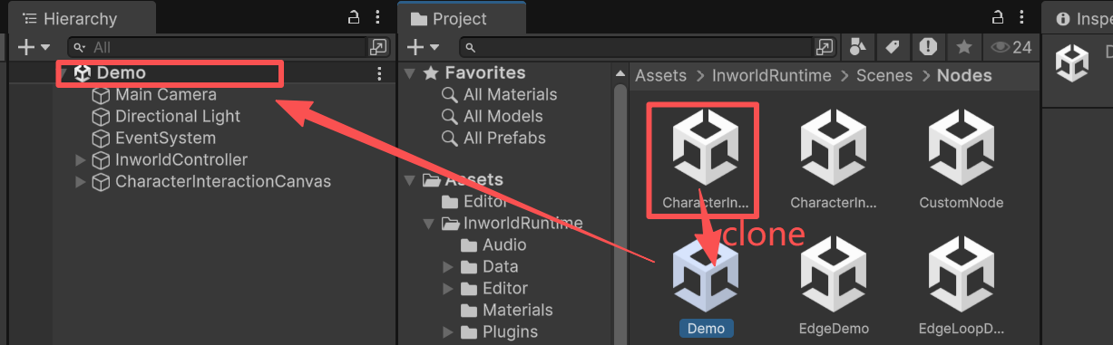
Assets/InworldRuntime/Scenes/Nodes/CharacterInteractionNode.unity.Let’s rename the cloned one whatever you want. i.e; Demo, and open it.Check out the current Graph
The graph is held under the 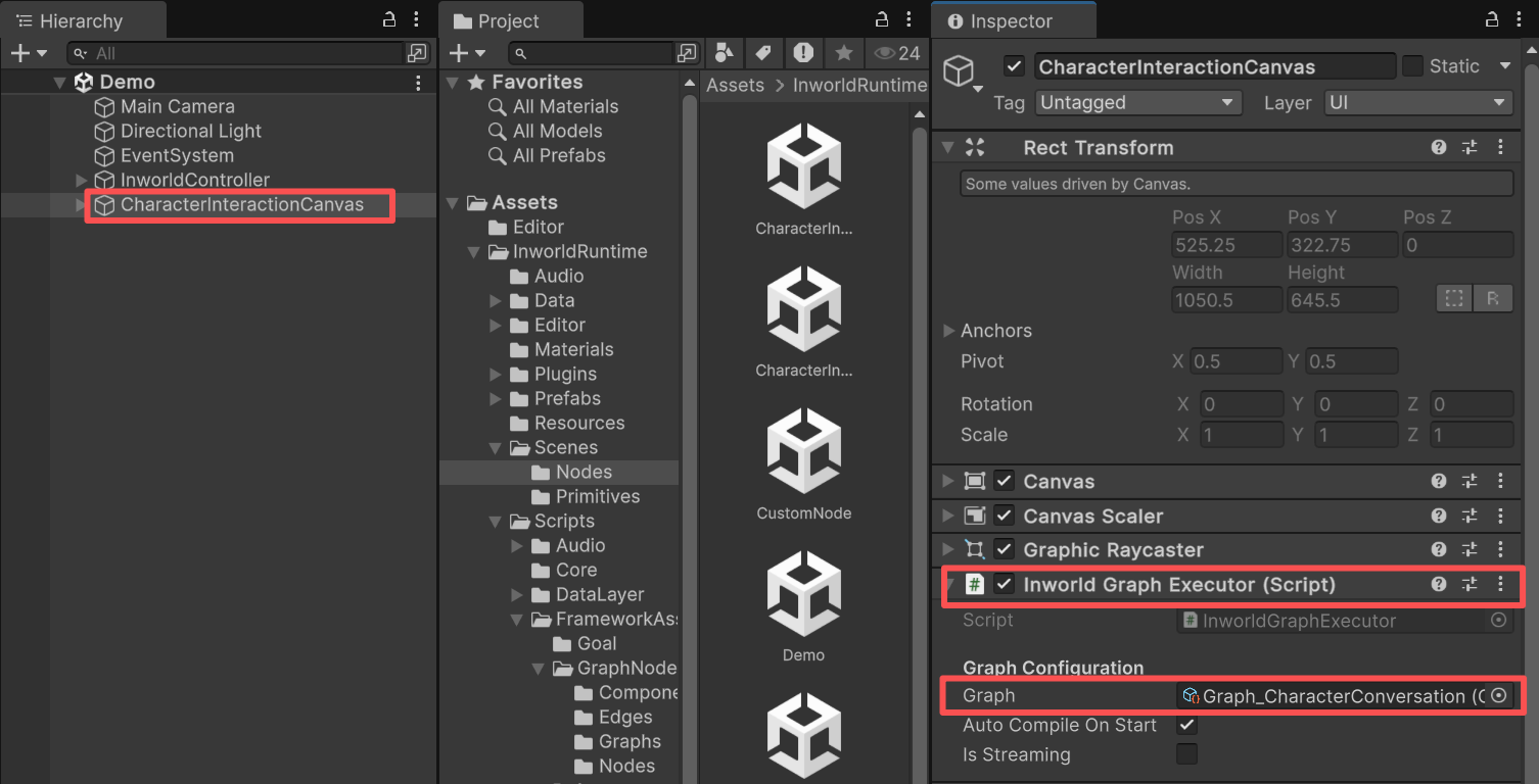
InworldGraphExecutor, which is at the root hierarchy of CharacterInteractionCanvas.Navigate to that place, double click the asset to open it in Inspector.Open Graph Editor button. Click it.Create your own Graph Asset
Create Graph
Right click on the 
Project tab, select Create > Inworld > Create Graph > CharacterInteraction.In the inspector, fill in the essential data. User data and character data are essential.
- User Data
- Character Data (In Characters list of the Character Interaction Data).
- Voice (If you’re planning to use TTS)
- Prompt (if you’re planning to use LLM)
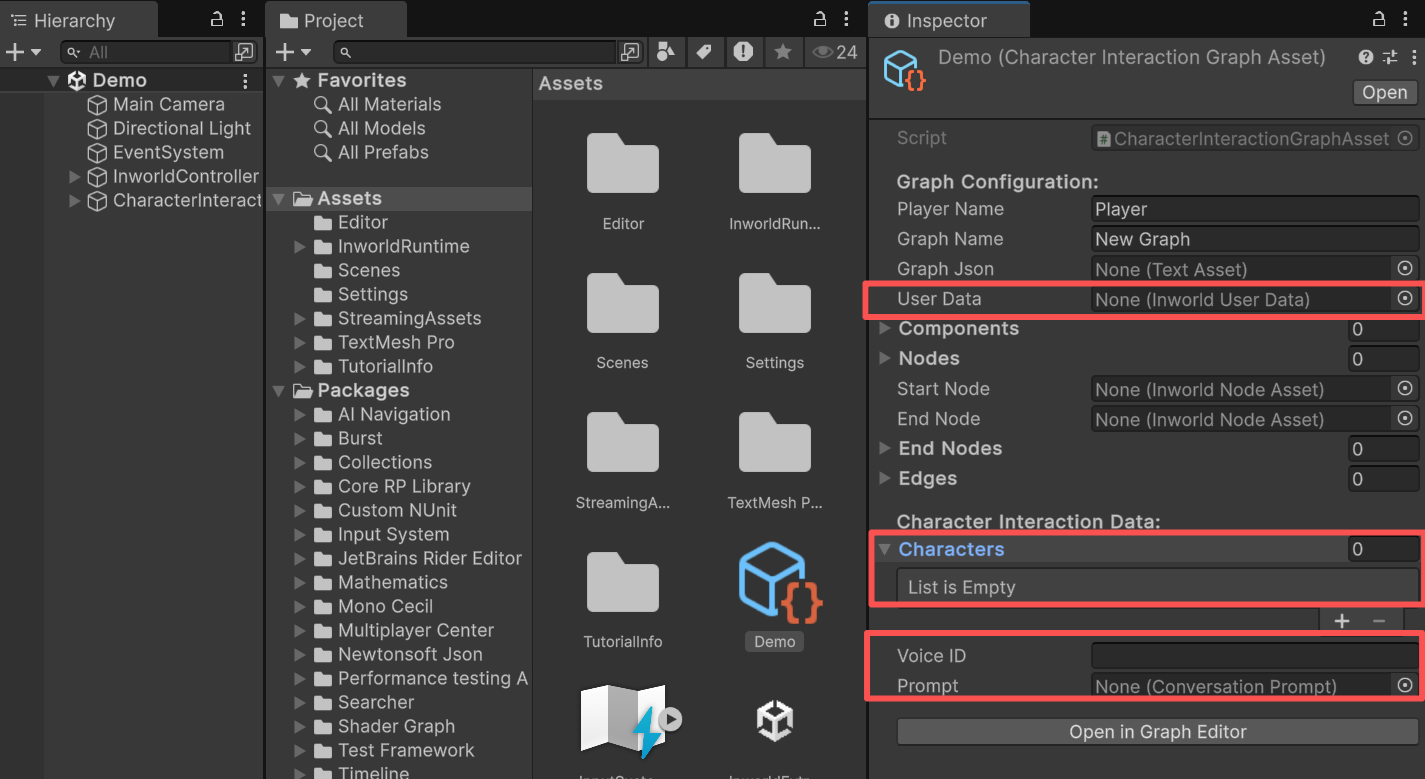
You can click the 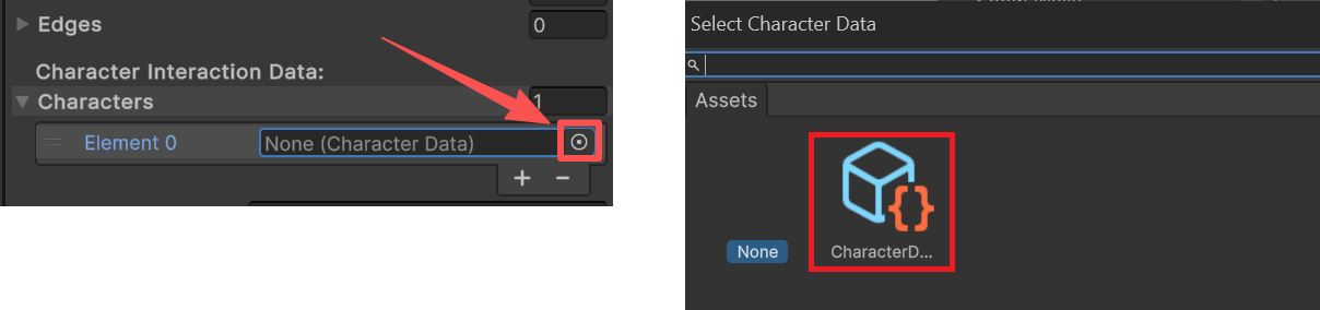
◎ icon to select the default one first.Then clone and update your own data later.Edit your Graph
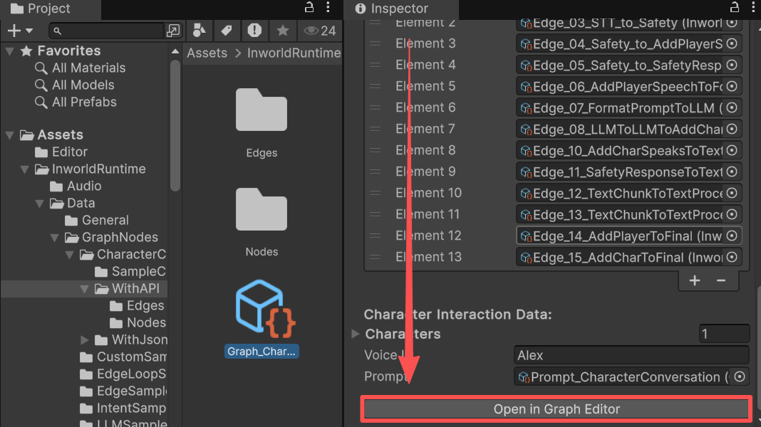
Open Graph Editor
Once the character data and the user data has been set, let’s click the 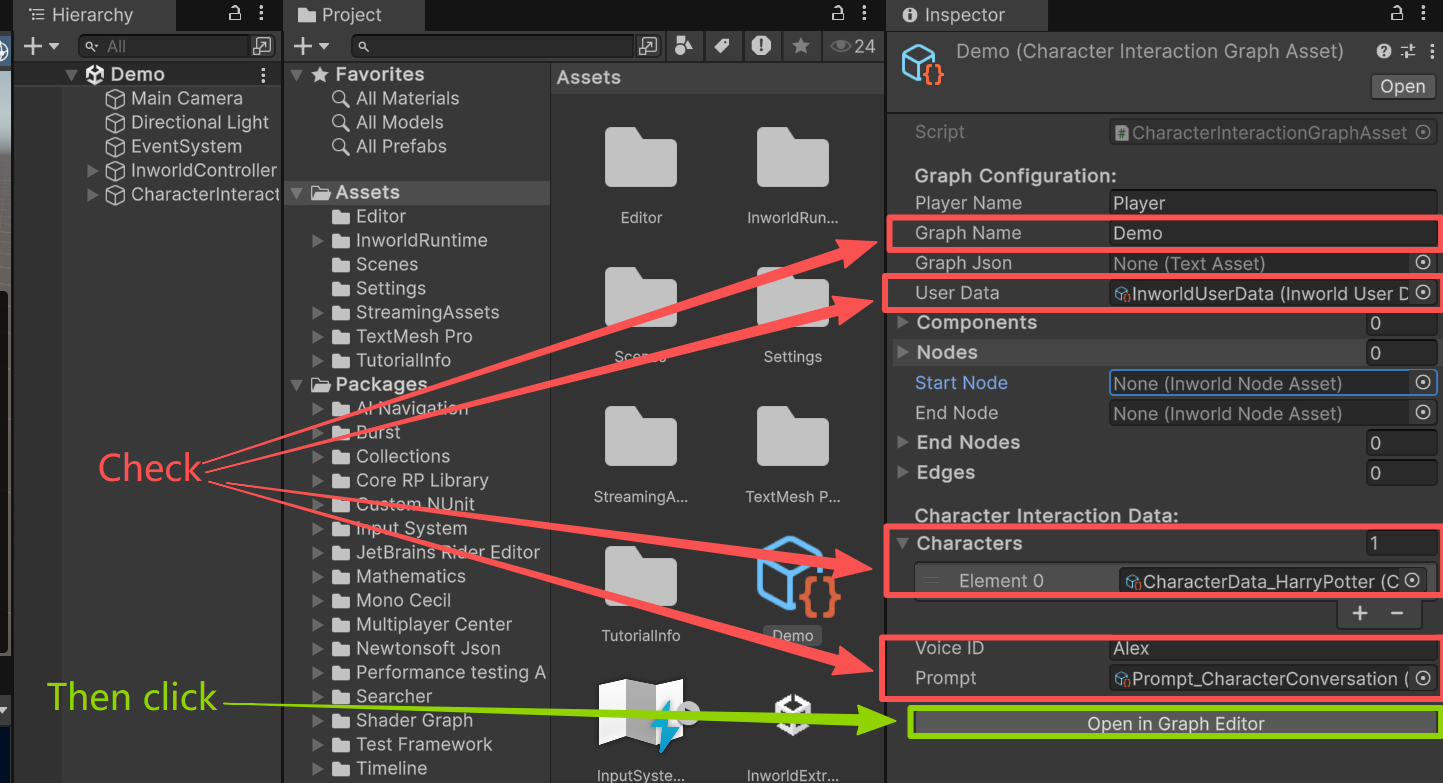
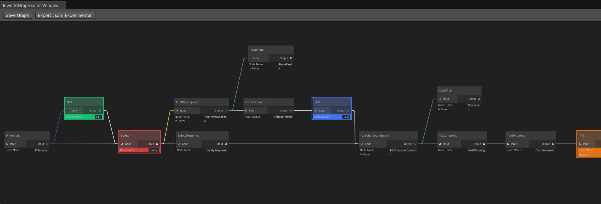
Open in Graph Editor button.Create a FilterInputNode
Right click on the Graph Editor, select 
Create Node > Custom Nodes... > FilterInputNode.Rename it to Input.Each node has to be renamed and has a unique name after created.
The graph compiler will fail if it found duplicated names.
FilterInputNode is good to be use as the StartNode, because you can use it to receive multiple input nodes.For example, currently it will detect if the format of the inputting data is correct.If the Inputting data is InworldText or InworldAudio, it will pass, otherwise it will fail.Currently, this node only support
InworldText and InworldAudio.
But please feel free to inherit this FilterInputNodeAsset and add your desired input type on your own.
(Still must be a existing child class of InworldBaseData though)Create a STTNode
From the output of FilterInput, hold left mouse button, drag an edge out.Create a
STTNode and rename it to STT.STT(Speech-to-text) Node is used to generate the text from player’s audio input.It accepts InworldAudio as input, sends InworldText as output.Create a AddSpeechEventNode
Right click on the Graph Editor, select 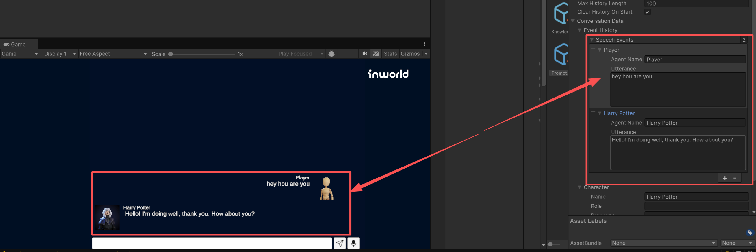
Create Node > Custom Nodes... > AddSpeechEventNode.Rename it to be PlayerSpeech.Set the IsPlayer to be true.The AddSpeechEventNode basically converts everything to InworldText.Meanwhile, it will store this piece of data in the ConversationData of the PromptAsset, which will later be used to generate the prompt.It’s expected to have a pair of AddSpeechEventNode, one for player, one for agent.By setting the
IsPlayer to be true, the generated data will be set into the prompt as the Player's speech.If not set, the agent will get confused with its identity.
Change Edge Types
Right click the edge from 
Input to STT, select Set Edge Type > Audio.Right click the edge from Input to PlayerSpeech, select Set Edge Type > Text.Connect to FormatPromptNode
Extend 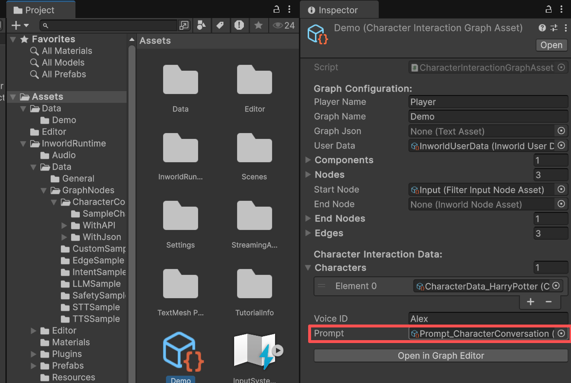
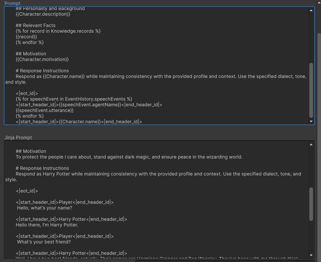
PlayerSpeech node out to create a FormatPromptNodeThe FormatPromptNode is a customNode. It converts InworldText to LLMChatRequest, that will be used in LLMNode as input.The FormatPromptNode will use the current graph’s prompt data. Set under the InworldGraphAsset you just filled.Prompt and JinjaPrompt.We will use jinja to take the previous node’s output, InworldText, together with the previously filled UserData, CharacterData to replace those {{}} defined the Prompt to generate the JinjaPrompt as the result.JinjaPrompt, is the actual data we are going to send to LLMNodeConnect to LLMNode
Extend
FormatPromptNode node out to create a LLMNode.The LLMNode is a dll node that cannot be inherrited.It takes LLMChatRequest as input, returns LLMChatResponse as output.Create another AddSpeechEventNode for Character
Extend
LLMNode node out to create another AddSpeechEventNode.Rename it to be CharacterSpeech.Set the IsPlayer to be false.Connect to TTSNode
Extend 
CharacterSpeech node out to create a TTSNode.Rename it to be TTS.Set the voice to be an available voiceID (Default is not an available ID right now. Please rename a valid voiceID)InworldText and InworldAudio as input, InworldAudio as output.It will take your typed or spoken speech as input, use STT to convert your audio into text, pasted in the current prompt, get the response, then speak out with TTS.Save your graph
You can simply press 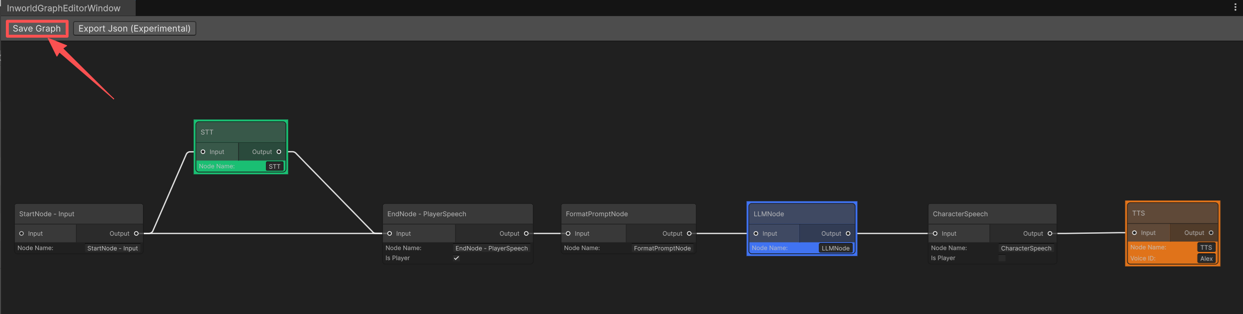
Ctrl + S or press the Save button at the top to save this graph.Asset/Data/{GraphName}Test your Graph
Apply your graph
Find the 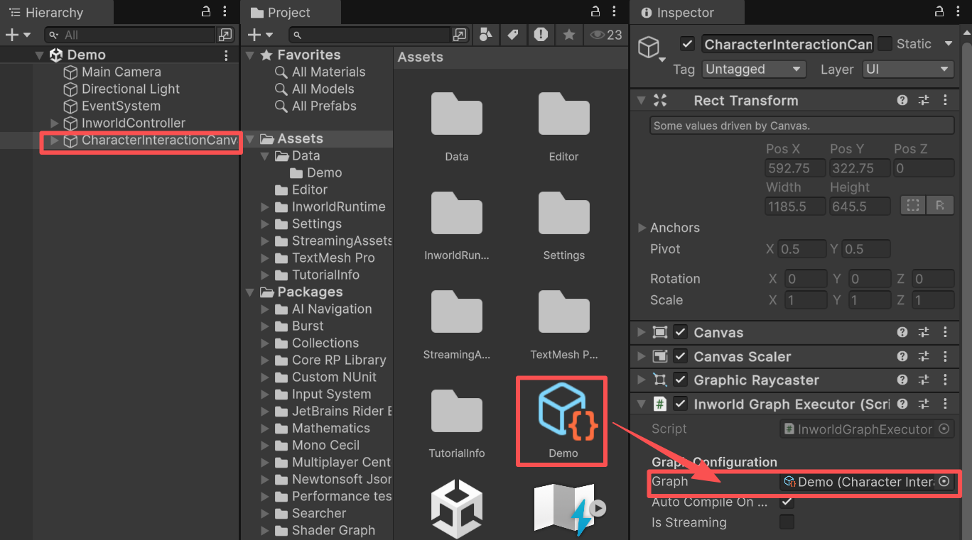
InworldGraphExecutor, by default it’s at the CharacterInteractionCanvas.Replace the graph asset with the one you just created.Update your Graph
Add ConversationEndpointNodes
Open your graph editor, adding
ConversationEndpointNode right after each AddSpeechEventNode (CharacterSpeech and PlayerSpeech)The ConversationEndpointNodes is a customNode that often used as EndNodes, it will generate the sentence like {Speaker}: {Contents}.For the user to extract and render correspondently.Rename ConversationEndpointNodes
- Rename the one after
CharacterSpeechtoCharacterFinaland set theIsPlayerto befalse. - Rename the one after
PlayerSpeechtoPlayerFinaland set theIsPlayerto betrue.
Save the graph
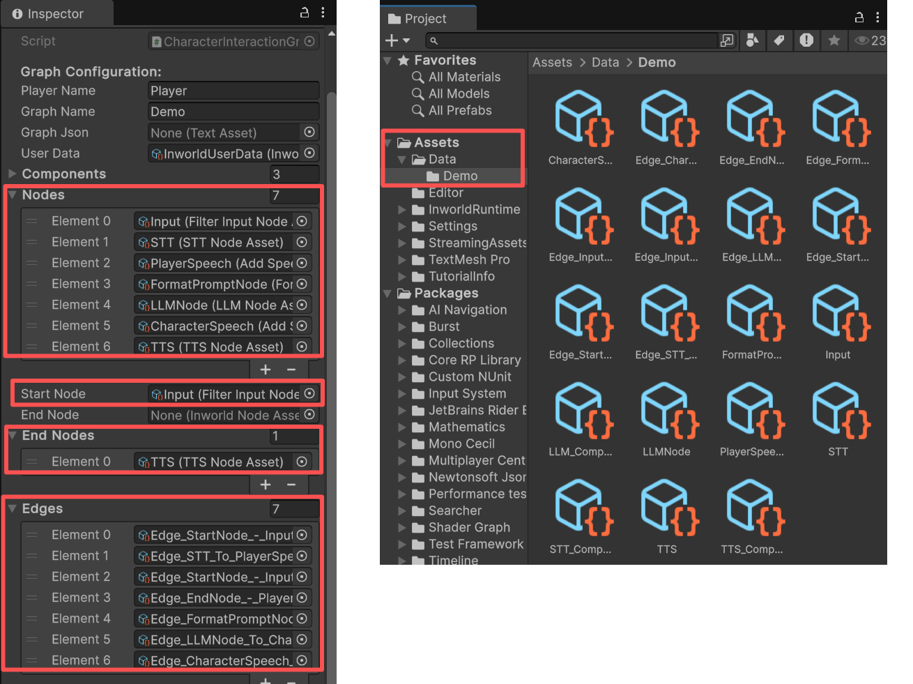
Press “Save”, you will see the data of the 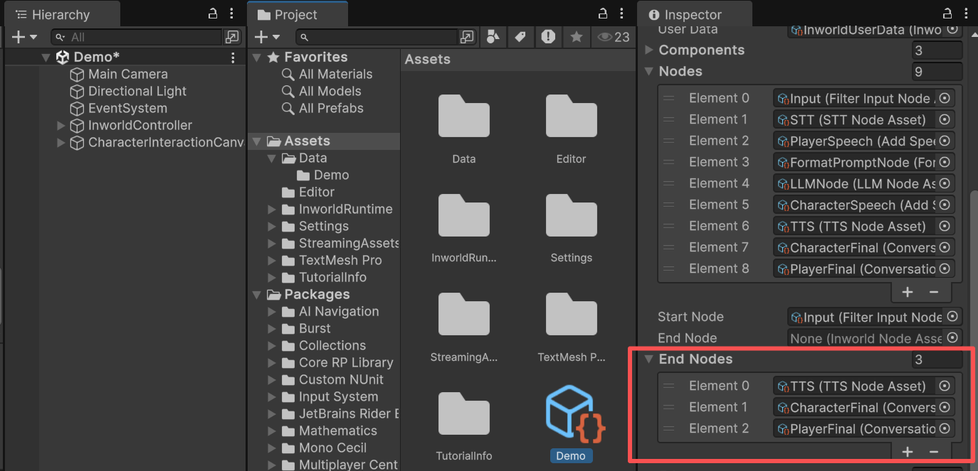
GraphAsset has changed.The EndNodes now contains 3 nodes.\